- All
- Product Name
- Product Keyword
- Product Model
- Product Summary
- Product Description
- Multi Field Search

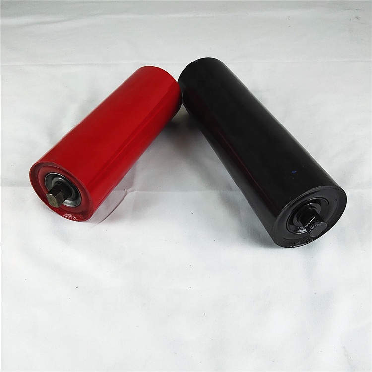


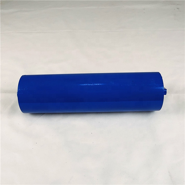
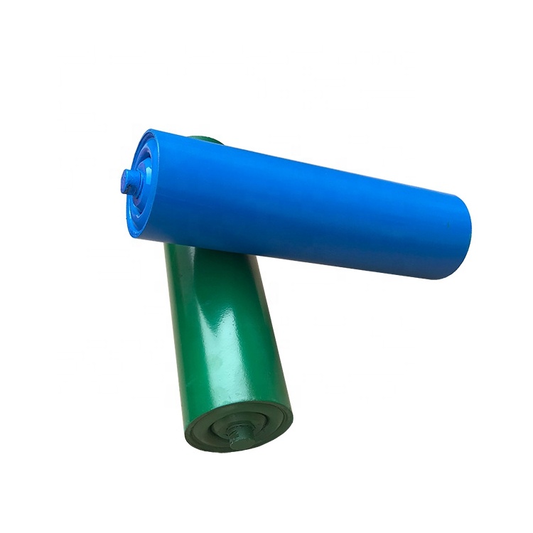
Idler/Roller is designed to support the belt and materials on the belt, so as to ensure the belt moving steadily.
1. Trough idler: used to bear branch loading (upper branch), consists of 350, 450, and 350 in common use.
2. Trough front inclination idler: 35°trough front inclination idler, of which side roller is 1.50 front inclined toward moving direction, so that centralizes the belt and prevents the belt from deviation.
3. Transition idler: It is located between the head or tail pulley and the first trough idler group, changes gradually the belt from flat shape to groove shape, or from groove to flat, so as to decrease the local tension of local tension of belt while the belt changes its shape suddenly, to lower the loss of materials. Transition idler consists of three types with angles as 100,200,300.
4. Flat carrying idler is used to transport mass materials.
5. Impact idler and impact bed is erected under the skirt plate of feeding section, aims at adsorbing the impact energy of materials while falling down, extending the lifetime of belt. It contains of two kinds of trough rubber ring impact idler and impact bed, 350 and 450.
6. Centering idlers have four types: vertical type, frictional type, conical type and self-aligning type. Centering idlers are used for avoid belt deviation.
7. Return idler is divided into flat shape, V-shape inclined type, V-shape with rubber rings, spiral type and reverse V-shape etc. V-shape and V-shape front inclined return idlers are used in wide belt conveyors, to centralize unloading belt. Assemble V-shape and reverse V-shape idlers together to be more efficiency-shape rubber rings and spiral idler can clean up the adhesive materials to keep the belt clean and avoid deviation.
8. Idler spacing
The spacing of idlers for carrying branch is between 1000 mm and 1200 mm. The spacing for unload branch is between 2400 mm and 3000 mm. The spacing between convex curve section and the concave one is determined through calculation, and it is usually 500 mm to 600 mm. The spacing for impact idler should be determined on the basis of the density, fragment size and the height could be set to 1/2~1/3 the spacing between trough idlers.
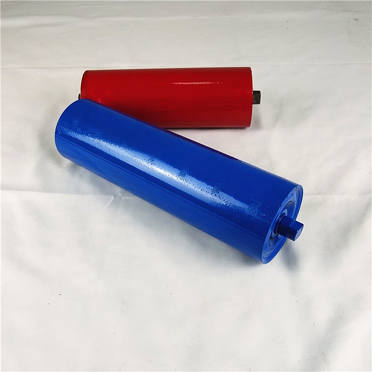
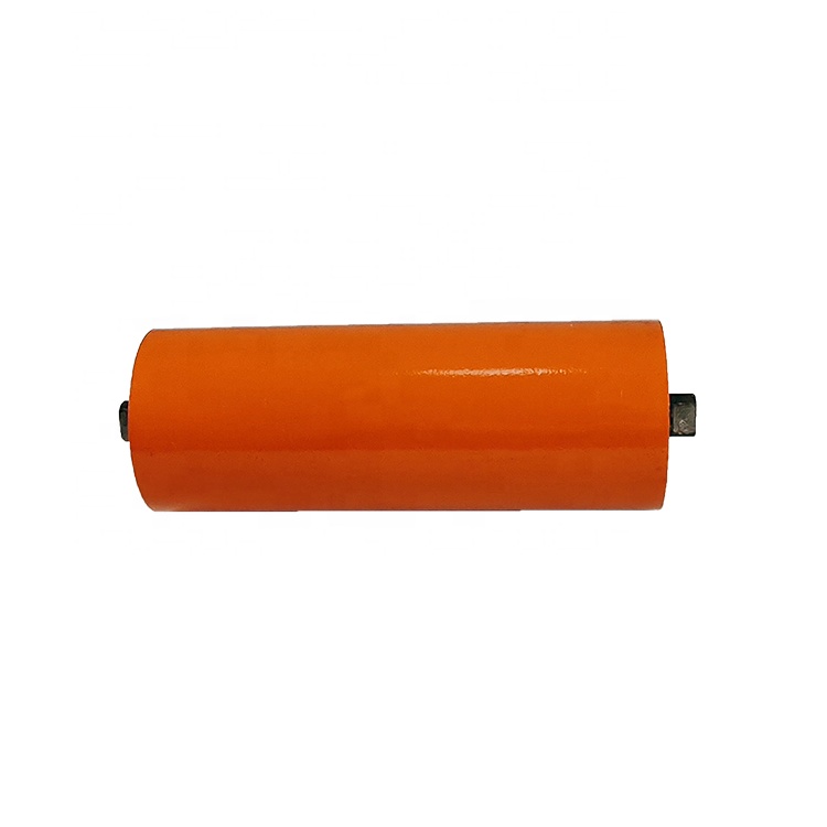
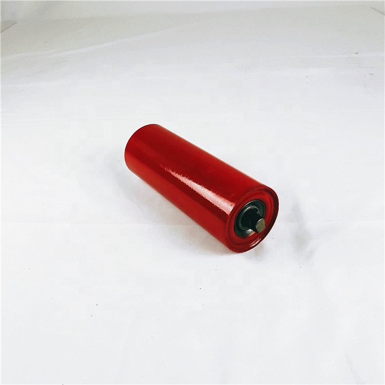
9. Rollers
The idler uses the punching bearing pedestal which is connected, by welding, to a super fined pipe with a cut. The inner structure is organized with big play bearing, polished shaft and the double labyrinth seal structure, with advantages as high precision, good sealing performance, light, long useful life, etc.
10. Detail parameters
1) Lift time: 50000hours
2) Production capacity: as usual 600000/year.
3) Idler Diameter: 76-219mm(non-Standard supported).
4) Idler Length: 190mm to 3500mm.
5) Idler tube: Q235 carbon steel, high-precision ERW, welded with DIN2394 Standard.
6) Bearing: Deep groove ball bearing 2RZ and 2Z with C3 clearance
7) Bearing brand: SKF, LYC, ZWZ etc.
8) Color: according to clients’ requirement.
9) Finish: Ordinary painting/hot galvanized painting/rubber/steel screw/galvanized
10) Welding: Mixed gas shielded arc welding /Automatic CO2 gas shielding welding
11) Standard: ISO/BS/JIS/DIN//CEMA/Australia
12) Package: standard export cases or iron cage with protective bubble film.
Idler/Roller is designed to support the belt and materials on the belt, so as to ensure the belt moving steadily.
1. Trough idler: used to bear branch loading (upper branch), consists of 350, 450, and 350 in common use.
2. Trough front inclination idler: 35°trough front inclination idler, of which side roller is 1.50 front inclined toward moving direction, so that centralizes the belt and prevents the belt from deviation.
3. Transition idler: It is located between the head or tail pulley and the first trough idler group, changes gradually the belt from flat shape to groove shape, or from groove to flat, so as to decrease the local tension of local tension of belt while the belt changes its shape suddenly, to lower the loss of materials. Transition idler consists of three types with angles as 100,200,300.
4. Flat carrying idler is used to transport mass materials.
5. Impact idler and impact bed is erected under the skirt plate of feeding section, aims at adsorbing the impact energy of materials while falling down, extending the lifetime of belt. It contains of two kinds of trough rubber ring impact idler and impact bed, 350 and 450.
6. Centering idlers have four types: vertical type, frictional type, conical type and self-aligning type. Centering idlers are used for avoid belt deviation.
7. Return idler is divided into flat shape, V-shape inclined type, V-shape with rubber rings, spiral type and reverse V-shape etc. V-shape and V-shape front inclined return idlers are used in wide belt conveyors, to centralize unloading belt. Assemble V-shape and reverse V-shape idlers together to be more efficiency-shape rubber rings and spiral idler can clean up the adhesive materials to keep the belt clean and avoid deviation.
8. Idler spacing
The spacing of idlers for carrying branch is between 1000 mm and 1200 mm. The spacing for unload branch is between 2400 mm and 3000 mm. The spacing between convex curve section and the concave one is determined through calculation, and it is usually 500 mm to 600 mm. The spacing for impact idler should be determined on the basis of the density, fragment size and the height could be set to 1/2~1/3 the spacing between trough idlers.
9. Rollers
The idler uses the punching bearing pedestal which is connected, by welding, to a super fined pipe with a cut. The inner structure is organized with big play bearing, polished shaft and the double labyrinth seal structure, with advantages as high precision, good sealing performance, light, long useful life, etc.
10. Detail parameters
1) Lift time: 50000hours
2) Production capacity: as usual 600000/year.
3) Idler Diameter: 76-219mm(non-Standard supported).
4) Idler Length: 190mm to 3500mm.
5) Idler tube: Q235 carbon steel, high-precision ERW, welded with DIN2394 Standard.
6) Bearing: Deep groove ball bearing 2RZ and 2Z with C3 clearance
7) Bearing brand: SKF, LYC, ZWZ etc.
8) Color: according to clients’ requirement.
9) Finish: Ordinary painting/hot galvanized painting/rubber/steel screw/galvanized
10) Welding: Mixed gas shielded arc welding /Automatic CO2 gas shielding welding
11) Standard: ISO/BS/JIS/DIN//CEMA/Australia
12) Package: standard export cases or iron cage with protective bubble film.


